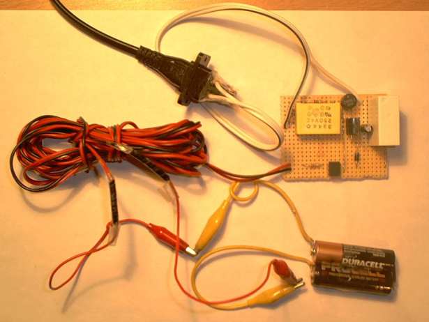
This is the much cheaper version, of a switched 16A wire. Against the 12 € material costs for the solid state relay stands:
1 € for a rectifier or 4 diods, 1.5 € for the voltage regulator ic, and 1.2 € for the optocoupler which realizes the galvanical separation from the Pc power suply, a few cents for the rest and last but not least the expensive relais for 4 €. But you need artless a few houres more to put all together. So if you do not have a electric soldering iron I recommend you to buy the little more expenive solid state relais, which you can see in my coffee maker.
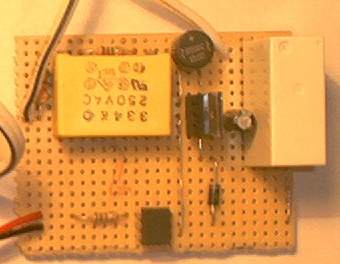
Top view of the relay card with condenser, rectifier, voltage regulator ic, 24V-relay, optocoupler, diode, capacitor and resistors. |
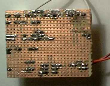
This is how the whole from down looks. Or shold I say: "Please: my PCB layout" (printed circuit board). |
part list:
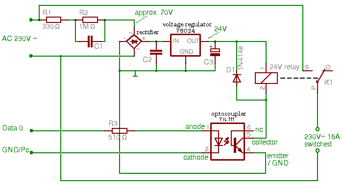
In principle the function of this card is very simple:
There is a relay, which could switch the 16A, 230V for you, the problem: You have to switch the relay too, but the parallel interface delivers not enough power for the magnetic field which tog the contact. So don't try it out, or your parallel interface could take some damage. The solution is to switch the relay not direct, but with an transistor. And for galvanical separation of your Pc with this card, you better put an optocoupler between them. Fortunately there were optocoupler with included transistor as amplifier like Til 111, with that you could switch the relay directly.
That's the principle. The Resistor three (R3) is only needed, because the optocoupler Til111 doesn't tolerate a voltage abouve 3Volts, and your par-port outputs 5. The diode D1 is a return diode, which is needed by every relais because of it's coil, the magnetical field and the switching optocoupler which not resist the glitch which accrue if a coil, flown by power, gets switched off, since the magnetic field induced a voltage in the coiled wire.
The rest is the power suply for the relais and optcoupler:
The two resistors R1 and R2 and the fat condenser C1 are for breaking down the mains voltage to approx. 70V without a big and expensive transformer, but attention you don't have a galvanical separation here. The following rectifier, or 4 diodes if ya want, commutate the voltage, which the voltage regulator ic breaks again down to 24V, with final smoothing by C3. C2 is only needed for elemination of the swing inclination of the v.reg. ic.
That's all, it works fine, but I won't take any warranty for your wiring, and don't try to build this circuit with a 12V relay and voltage regulator ic, it woun't work because the R2 (1M Ω) won't let enough power through for switching the relay.
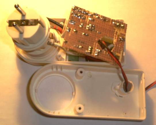
The installation in the case from a retired time switch clock, where the idea from the power supply comes from. They made it with a resistor, z-diode, transistor and the fat condenser C1 which I've taken over.
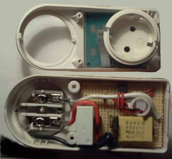
As well as finished ...
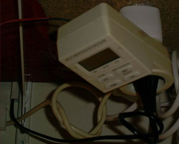
Voilą: Mine with Pc controllable 16 A switch, which stears my lavalamp at present.
It's really more pleasant to stand up in wintermorning if music plays, the light is already on and the coffee is available for you. ;)
With the linux cronjob every day on another time if it should be, how that works ? - Lern German :) and read it in my linux crash course, or have a short look at my example under the crontab article in chapter 2.8! So much fun switching your house.